An Introduction to Radio Direction Finding
Military, Rescue, and Scientific Applications of RDF Technology
From its roots in 1990, Alaris Antennas has grown to become a substantial supplier of advanced Electronic Warfare (EW) antennas. For the global defence and security markets, Alaris Antennas’ mission is to deliver high-quality antenna solutions, on time, through technical and service excellence. Alris Antennas supplies innovative, customised antennas and related RF product solutions to global RF system integrators.

Humans do audio direction finding to a remarkable precision of less than two degrees. Shortly after the development of radio transmitters and receivers, radio direction finding (RDF or just DF) evolved for much the same reasons as human audio direction finding: firstly, for the location of possible threads and secondly for spatial awareness.
RF direction finding is used in a number of applications:
1. Military: such as the direction of a thread, the location and movement of enemy transmitters
and the direction of enemy jammers.
2. Search and Rescue: the location of RF search and rescue beacons.
3. Science: the tracking of animals in their environment.
4. Radio monitoring: the location of sources of interference and of illicit transmitters
Terminology and Abbreviations:
RF: Radio Frequency
• DF: Direction Finding
• RDF: Radio Direction Finding
• AOA: Angle of Arrival
Two Receiver Direction Finding Systems
Directional Antenna Technique
The accuracy of this technique is dependent on the width of the antenna radiation pattern. A narrow beam will improve the accuracy but will increase the time spent scanning all possible directions. If the beam is too narrow the target may even be missed especially with intermittent transmission sources. A broad beam will decrease the bearing accuracy. Scientists use handheld RDF devices to follow and accurately locate wild animals once their general location is known. Radio beacons can be made very small and consume very little power. This is ideal for long-duration tracing of even very small animals.
The relative signal strength is used to determine the direction of the radio beacon and the absolute signal strength shows some measure of the distance to the radio beacon. In military applications this RDF is called a Spinning DF system and is commonly used for broad band high frequency DF. These systems are fully motorized and use knowledge of the antenna radiation pattern to improve accuracy.
The benefit of a single receiver RDF system is that they are cost effective, compact and have low power consumption. The Figure 1 (to the right) shows both a wide and narrow beam as they scan for signals transmitted by the target. The received signal level of both beams can be seen on the left. Note how the signal levels increase the closer the beams are to the direction of the target.
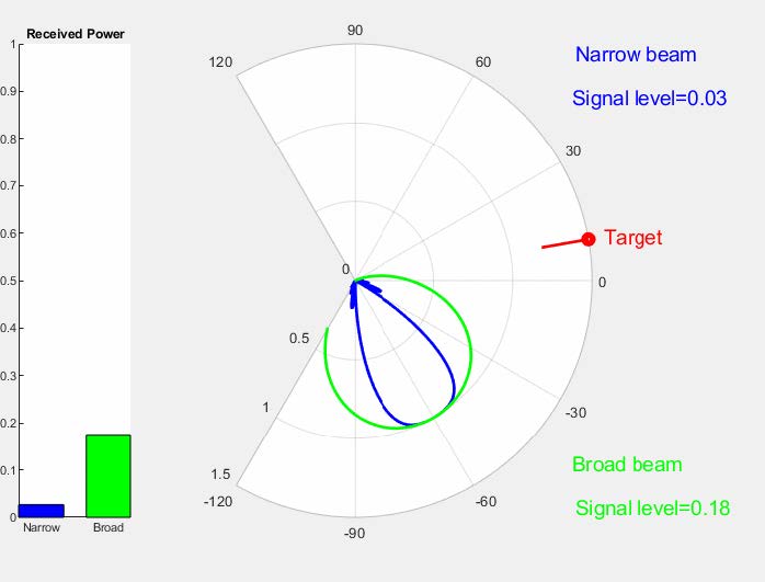
The simplest RF direction finding system consists of a directive antenna and a single receiver. The antenna is pointed in different directions while the receiver indicates the received signal strength. Only the magnitude of the signal is used to determine the direction of a transmitter.
Doppler and Pseudo-Doppler Direction Finding Technique
The Doppler direction-finding system uses a single receiver connected to an omnidirectional antenna physically rotated on the circumference of a circle. As the antenna moves toward the radio source, the Doppler shift increases the received frequency, and the received frequency decreases as the antenna moves away from the source. The change in frequency (obtained by FM demodulation) is used to determine the direction of the radio source.

The modern approach is to successively sample each antenna in a circular array of antennas, removing the need for any moving parts. This is referred to as Pseudo Doppler Direction Finding.
The image in the left of the figure below shows the circular trajectory of a Doppler Direction-Finding Antenna. The received signal is incident from the right.
The received frequency at various positions along the trajectory of the antenna is shown in the right image of the figure. As the antenna moves away from the incident signal, the frequency increases (red graph) and as the antenna moves towards the incident signal, the frequency increases (blue graph). The black curve shows the received frequency response at the position indicated by black circle on the antenna diagram.
Monopulse Direction Finding Method
The monopulse or sum-difference RDF technique uses two antennas. The antennas are connected to a four-port combiner 180° hybrid that generates a sum and difference signal.
Such sum and difference patterns are generated by means of closely spaced overlapping radiation patterns at boresight. These signals form sum and difference radiation patterns. The ratio of the sum and difference signals and knowledge of the sum and difference patterns are used to determine the direction of the transmitter.
Phase information is used to determine on which side of the sum pattern the transmitter is. An advantage of this system is in its capability to determine the direction of a transmitter after receiving one pulse. Such pulse could be a mere few microseconds. Accuracies of 10meter over a 100Km distance has been reported.


Interferometric Direction Finding
The relative difference in the phase of the signal received by two omni-directional antennas spaced a set distance apart can be used to determine the direction or angle of arrival of an RF signal.
In the omni directional case, the interferometer does not have a way to determine if the signal arrives from the front or the back of the antennas.
As the frequency increases (or electrical separation increases) ambiguities appear as the phase differences wrap. If the antennas are too close (electrical separation very small) then the resulting phase difference will be very small and the system will not be able to determine the AOA. The frequency range of use is thus determined by the separation of the antennas and the noise figure of the receivers.
The image below shows two omni-directional antennas with the incident signal circulating around them. The relative phase of the incident signal between the two antennas is shown in the image on the right. This phase difference is used to determine the direction of the incident signal.
Adcock Antenna, Watson-Watt Method
An Adcock antenna uses two crossed loop antennas. The bearing of the RF signal is determined using the level of the signals received at each antenna. The method to process the information from a Adcock array is referred to as Watson-Watt. This is the best known method of radio direction finding.
In a more general application four closely spaced omni-directional antennas positioned in a square can be used to form an Adcock array. The opposing antennas are combined using a 180° combiner to form figure-of-8 patterns, which creates a unique set of magnitudes for any bearing direction.
A Watson-Watt antenna cannot determine if a signal comes from the front or the back without the use of a third omni directional antenna to resolve the 180° ambiguity.
The figure below shows the typical radiation pattern of an Adcock array. The received signal rotates around the array. The relative amplitude of the signal received by the two crossed-loop antennas (or combined omni-directional antennas) is shown on the right. The + and – at the top indicates the relative phase of the two crossed loops with respect to the omni. It is this relative phase that resolves the ambiguity.


N Receiver Systems – Correlative RDF
With the technological improvements in receivers and digital processors, all the information produced by multiple antenna elements can be used to improve the performance of RDF systems. Typically, the bearing is calculated using the phase differences of the signals received at the various antennas in the correlative array.
The correlative algorithm compares the phase differences of the incoming RF signals at each antenna to a set of calibration phases stored in the processor to determine the most likely AOA. The correction function correlates the relative phases (and magnitudes for some correlators) of the received signals with the correlation table over all possible angles; the maximum of the correlation function indicates the AOA. The calibration information can be obtained by calculation or by measurement of the antenna.
The most common implementation of a correlative array is to have several omni directional antennas (typically four to nine antennas) in a circular pattern. In this configuration the differences in the phase of the incoming RF signal at each element is used by the correlative algorithm to determine the AOA.
Cutting edge systems can use both magnitude and phase of an arbitrary number of antennas arbitrarily positioned to determine the AOA in 3D, not just in a horizontal plane. The spatial positioning of the antennas in the array is of critical importance to achieve good performance without introducing ambiguities.
3D calibration data (not just in azimuth but also in elevation) with elements spatially positioned in atypical configuration is used to determine the AOA in 3D. In many practical applications the patterns of the antennas will not be omni directional, clever algorithms can incorporate the magnitude information to improve RDF performance.
Even an Adcock antenna can be characterized and used in conjunction with a corelative estimator to improve performance of the Watson-Watt method.
RDF Performance
The two critical performance measures for DF systems are accuracy and sensitivity.
Accuracy is the measure of how accurate the bearing direction can be determined. The accuracy of a DF system is dependent on the DF processor, the specific design, the quality of the antenna elements used and the installation environment of the antenna.
Sensitivity is the measure of how well the DF system will perform in the presence of a small signal in a specified noise level. The sensitivity is dependent on the receiver noise, losses in the antenna and even the topology of the antenna elements in the array.
Get expert advice
Alaris Antennas' direction finding antennas are available for purchase from APC Technology. For technical advice and details about other antennas, you can speak to one of our RF and Microwave specialists. Contact a member of our team or arrange a meeting to discuss your applications and projects.