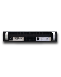
7548
7548
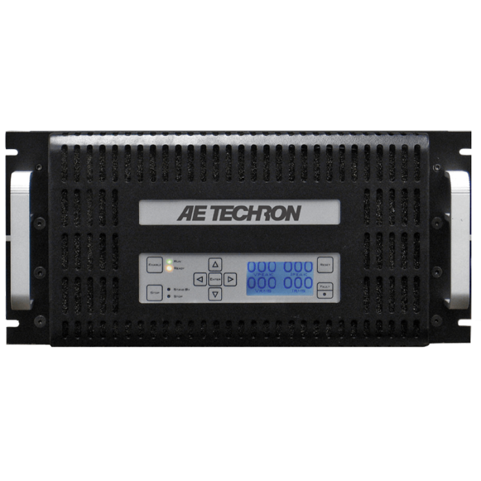
AE Techron
Industrial Amplifier for Pulse or Continuous Duty
Up to 100 Ap/195 Vp, DC to 100 kHz, Three-Phase
- Field-selectable controlled-voltage or controlled-current operation
- Can be switched between rail supply modes to optimize for various load impedances
- Protection circuits guard against over/under voltage, over current, over temperature, and circulating ground currents
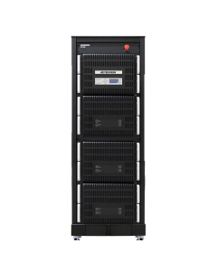
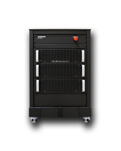
The 7548 amplifier is a DC-enabled, high-powered unit designed to provide very low noise and fast slew rates. A single 7548 has an output capability of 100 amperes peak and 200 volts peak when driving typical MRI gradient coil loads. It can output a 40 ms pulse with up to 105 amperes peak current into a 1-ohm load. If more current is needed, up to four amplifiers can be combined in series or parallel and operate as a single system.
The 7548 can operate in either voltage or current mode and features robust output devices and a power range of over 3300 watts RMS. It can safely drive a wide range of resistive, inductive loads.
Typical use includes as a power source for EMC testing in applications that require both continuous AC or DC signals and significant short term (burst) signals. It can be combined in a three-phase system ideal for MIL-STD-704F (AC and 28V DC tests).
Key Performance Capabilities:
- Over 12,000 watts peak for 40 ms and 5,500 watts peak continuous into a 1Ω load
- 40 ms pulses of up to 105 Ap into a 1Ω load
- Frequency bandwidth of DC-50 kHz at rated power; DC-100 kHz at reduced power
- Continuous system output of 800 Vp or 170 Ap maximum are possible with multiple, interconnected amplifiers
Click below to request a quote for this item. Or for product advice, stock and lead time enquiries call our team on 0330 313 3220.
| Attribute | Value |
|---|---|
| Protection |
Over/Under Voltage: ± 10% from specified supply voltage amplifier is forced to Standby Over Current: Breaker protection on both main power and low voltage supplies Over Temperature: Separate Output transistor, heat sink, and transformer temperature monitoring and protection |
| Physical Characteristics |
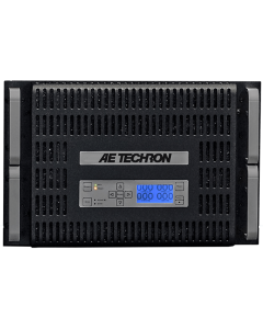
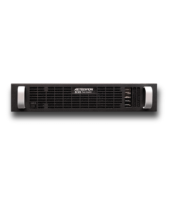
Chassis: The amplifier is designed for stand-alone or rack-mounted operation. The chassis is aluminum with a black powder-coat finish. The unit occupies five EIA 19-inch-wide units. Weight: 103 lbs (46.7 kg), Shipping 115 lbs (52.2 kg) AC Power: Three-phase, 208 VAC (±10%), 47-60 Hz, 20A AC service; (400 VAC (±10%), 15A model available) Operating Temperature: 10°C to 50°C (50°F to 122°F), maximum output power de-rated above 30°C (86°F). Humidity: 70% or less, non-condensing Cooling: Forced air cooling from front to back through removable filters via four 100-ft3/min. fans. No space is required between rack-mounted amplifiers. Air filters are removeable from the rear via one fastener per side and may be eliminated if cabinet filtration is provided. Dimensions (HxWxD): 8.75″ x 19″ x 22.8″ (22.2 cm x 48.3 cm x 57.9 cm) |
| Status Display, Control, I/O |
Front Panel LED Displays indicate: Ready, Standby, Fault Soft Touch Switches for: Run, Stop, Reset LCD Display: Can be configured for up to four simultaneous displays reporting one, two, or all four of the following: Vp, VRMS, Ap, ARMS Also reports any fault conditions that occur and suggests corrective action. Back Panel Power Connection: NEMA-style locking receptacle; matching AC connector also included Signal Output: 4-position terminal barrier block (OUTPUT / COMMON / SAMPLED COMMON / CHASSIS GROUND); resistor installed between SAMPLED COMMON AND CHASSIS GROUND is a 2.7-ohm, 2W, 5%, metal-oxide resistor Signal Input: User-selectable BNC or Barrier Strip, balanced or unbalanced Interlock Connector: 25-pin D-sub connector used for amplifier control and status applications; also used in multi-amplifier applications |
| Communication Capabilities |
Current Monitor: 20A/V ± 1%; 10A/V ± 1% (differential configuration) Reporting: System Fault, Over Temp, Over Voltage, Over Load Remote Control via Interlock Connector: Blanking control, Force to Standby, Reset after a fault |
| Frequency Response | +1.0 to -0.5 dB |
| 8-Ohm Power Response |
|
| Residual Noise | Less than 250 µV |
| Unit to Unit Phase Error | ±0.1 degrees at 60 Hz |
| DC Drift |
|
| Output Impedance | 3.2 mOhm in series with 2.2 µH |
| Phase Response | ±5 degrees plus 600 nsec propogation delay |
| Output Offset Current | Less than 10 mA, DC |
| Maximum Continuous Output Power | 3300 watts RMS |
| Power Sinking | 1.2 kVA at 120 VAC |
| Total Harmonic Distortion (THD) | Less than 0.25% |
| DC Offset | Less than ±200 µV |
| Slew Rate | >35 V/µs |
| Input Characteristics |
Balanced with ground: Three terminal barrier block connector, 20k ohm differential Unbalanced: BNC connector, 10k ohm single ended. Gain, Voltage Mode: 20 volts/volt; Current Mode: 5 amperes/volt Gain Linearity (over input signal, from 0.2V to 5V): 0.15% Max Input Voltage: ±10V, balanced or unbalanced Input Impedance: 20k ohm differential |
| Attribute | Value |
|---|---|
| Data Sheet | Click here to view |