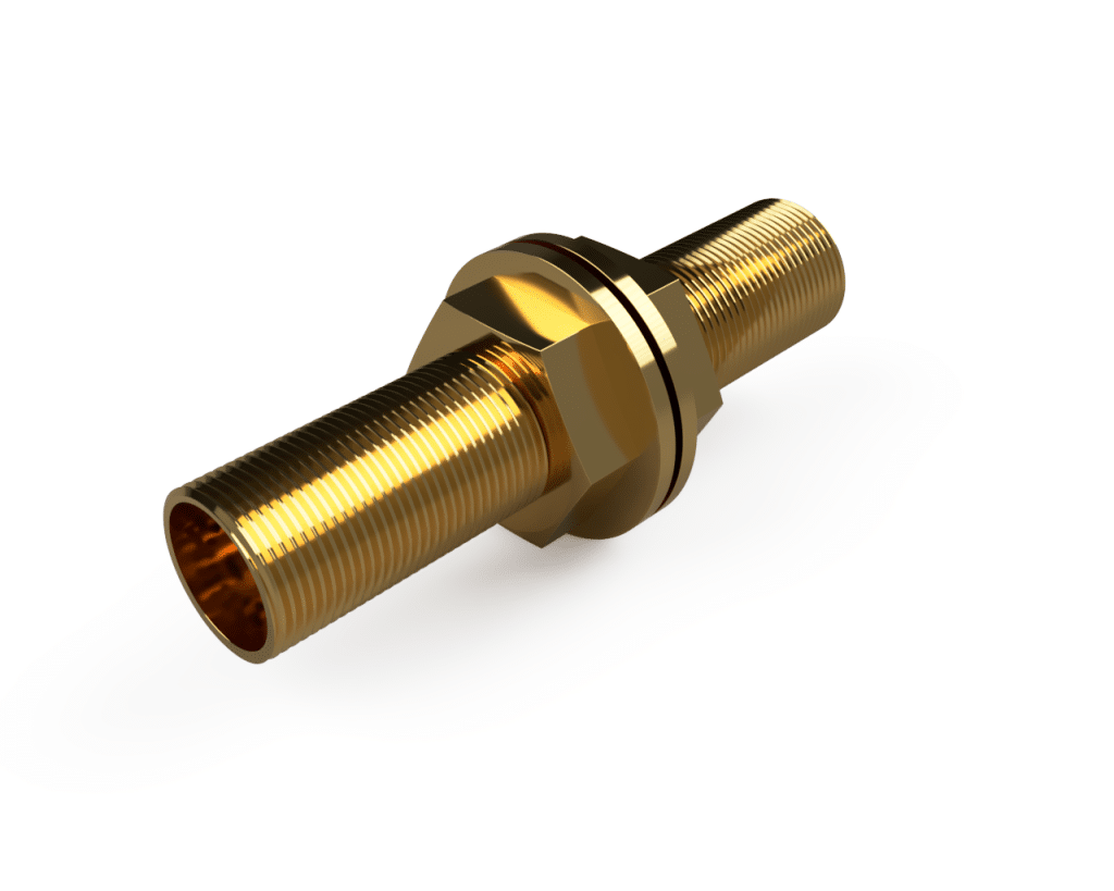
RF Pipe Penetrations (Waveguide Feed-Throughs)
When water, gas, fibre or air services pass into a shielded enclosure, every pipe penetration becomes a potential RF leak. A pipe penetration closes that gap by behaving as a waveguide below its cutoff frequency, so your utility passes through and the attenuation holds.
APC supplies the full ETS-Lindgren range, from ½" at 13.8 GHz to 4" at 1.7 GHz, with dielectric-union and honeycomb options for ground isolation and high-frequency work.
What an RF Pipe Penetration Does
An RF pipe penetration carries a non-conductive utility - water, gas, compressed air or fibre optics through the wall of a shielded enclosure without breaking its shielding effectiveness.
It works on the waveguide-beyond-cutoff principle. A circular tube acts as a waveguide, below its cutoff frequency, that waveguide attenuates RF heavily. The core diameter sets the cutoff frequency - the smaller the bore, the higher the frequency it blocks. The core length sets how much attenuation you get.
As a rule of thumb, keep the length at least four times the diameter. So a penetration is not a hole in the shield. It is a sized tube that lets your utility pass while the geometry keeps RF in or out.
Find your size - cut-off frequency by diameter
Cut-off frequency for a circular waveguide:
- fc = c / 3.412r
- fc = cutoff frequency
- c = speed of light, 1.181 × 10¹⁰ in/s
- r = radius of the circular waveguide, in inches
General rule of thumb:
Make the waveguide length at least four times its diameter.
Larger bores lower the cutoff, so they shield less at high frequencies. Above ½", you will not hold 100 dB at 10 GHz, size to your highest frequency of concern.
Fire suppression & VESDA pipe penetrations
Fire suppression and VESDA pipework are the most common reasons to penetrate a shielded room and the easiest place to lose your shielding effectiveness.
APC supplies pipe penetrations for water and gas fire-suppression feeds and for VESDA aspirating smoke-detection pipework. Each penetration passes the pipe while holding RF attenuation across the bore. Where conductive metal pipe runs to the penetration, fit a dielectric union. It breaks the metal path and keeps the single-point grounding that a shielded enclosure depends on. The penetrations are fully NPT threaded, so they connect to standard plumbing on the incoming side.
|
Pipe diameter |
Cutoff frequency |
|
0.5 in (1.27 cm) |
13.8 GHz |
|
0.75 in (1.91 cm) |
9.2 GHz |
|
1 in (2.54 cm) |
6.9 GHz |
|
1.25 in (3.175 cm) |
5.5 GHz |
|
1.5 in (3.81 cm) |
4.6 GHz |
|
2 in (5.08 cm) |
3.5 GHz |
|
2.5 in (6.35 cm) |
2.8 GHz |
|
3 in (7.62 cm) |
2.3 GHz |
|
4 in (10.16 cm) |
1.7 GHz |
Dielectric unions & Honeycomb inserts
Dielectric unions
Dielectric unions (part numbers 551083–551091) maintain isolation from ground. Use wherever conductive piping meets the shield, so you do not create a hard ground that degrades shielding performance.
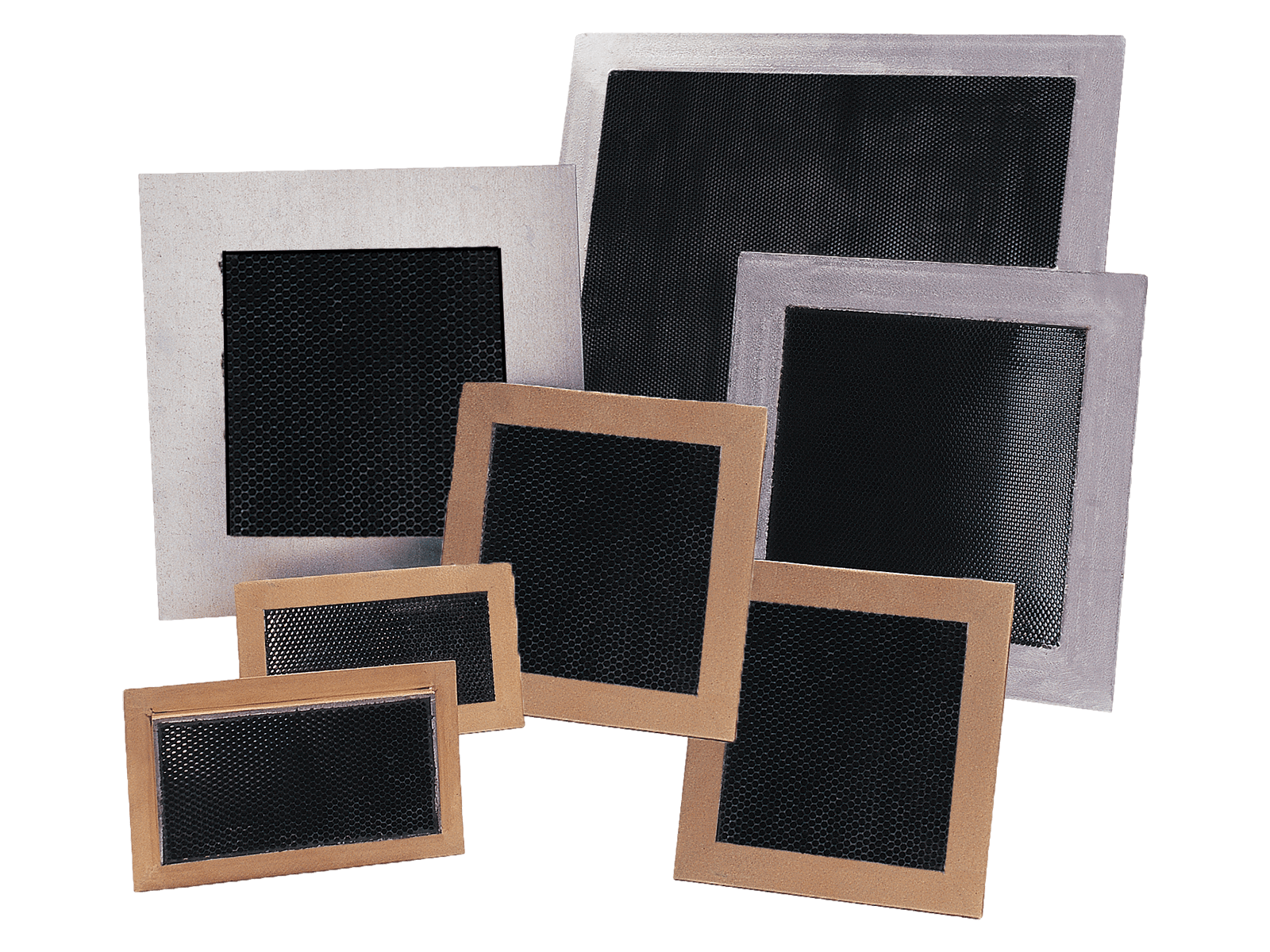
Honeycomb Inserts
Honeycomb inserts suit high-frequency or gaseous applications, where a single open bore would let too much RF through. The honeycomb subdivides the bore into many sub-cutoff cells, raising attenuation while still passing gas or air.
Part Numbers & Specifications
|
Waveguide Feed-through Part Number |
With Dielectric Option Part Number |
Nominal Pipe I.D. |
Length |
Installation Hole Size |
|
1.27 cm (.5 in) |
15.24 cm (6 in) |
2.22 cm ( .875 in) |
||
|
1.91 cm (.75 in) |
15.24 cm (6 in) |
2.86 cm ( .125 in) |
||
|
2.54 cm (1 in) |
15.24 cm (6 in) |
3.49 cm (1.375 in) |
||
|
3.175 cm (1.25 in) |
15.24 cm (6 in) |
4.46 cm (1.75 in) |
||
|
3.81 cm (1.5 in) |
15.24 cm (6 in) |
4.92 cm (1.9375 in) |
||
|
4.08 cm (2 in) |
20.32 cm (8 in) |
6.35 cm (2.5 in) |
||
|
6.35 cm (2.5 in) |
20.32 cm (8 in) |
7.30 cm (2.875 in) |
||
|
7.62 cm (3 in) |
30.48 cm (12 in) |
9.21 cm (3.625 in) |
||
|
8.16 cm (4 in) |
40.64 cm (16 in) |
11.75 cm (4.625 in) |
APC Technology Group can also manufacture specialty one-off pipe penetrations for unique applications
Contact our test team for a quote or for more information