
A Good VSWR Does Not Always Mean a Healthy LMR System
Looking Beyond The VSWR Reading
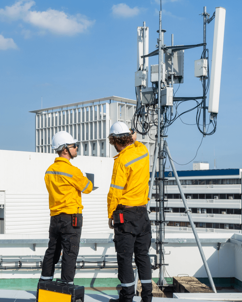
Voltage Standing Wave Ratio, or VSWR, is one of the most familiar measurements used during the installation, commissioning and maintenance of Land Mobile Radio systems. For many Land Mobile Radio (LMR) engineers, checking the VSWR of an antenna system is one of the first tests performed during installation or fault finding.
A low VSWR has long been considered a key indicator of a healthy RF system, with many organisations setting acceptance limits of 1.5:1 or better. The low reading indicates that the antenna system presents an acceptable impedance match and that relatively little RF energy is being reflected towards the transmitter.
However, modern LMR networks supporting emergency services, utilities, transport and critical infrastructure place far greater demands on RF performance than simply transferring maximum power from transmitter to antenna. Digital modulation schemes such as DMR, P25 and TETRA require consistent signal quality, stable link budgets and predictable coverage margins. VSWR therefore only provides part of the picture.
An antenna system can produce an apparently good VSWR reading while still suffering from excessive feeder loss, moisture ingress, damaged connectors or degradation elsewhere in the transmission path. In these circumstances, the transmitter may appear to be operating correctly even though less RF power is reaching the antenna.
For LMR networks in mission-critical environments, such as those supporting emergency services, utilities, transport and critical infrastructure, this distinction matters. A system can be electrically matched but still experience degraded performance, reduced coverage, or intermittent failures that directly impact operational reliability. This can translate to:
- Missed emergency transmissions
- Reduced coverage at cell edges
- Increased network handover load
- Longer fault resolution times
- Reduced service resilience
Key Engineering Insight
A good impedance match does not necessarily confirm that the complete RF transmission path is healthy or operating efficiently. VSWR alone is no longer sufficient to assess true RF system integrity.
What Does VSWR Measure?
VSWR is the measure of impedance match between the transmission line and antenna load. It describes the relationship between forward and reflected RF energy within a transmission line.
In a nominal 50-ohm RF system, a perfect impedance match would produce a VSWR of 1:1. As the impedance mismatch increases, a greater proportion of the transmitted energy is reflected towards the source and the VSWR value rises.
VSWR is therefore an important measurement for identifying issues such as:
- Antenna mismatch
- Open or short-circuit conditions
- Installation faults affecting return loss
- Damaged antenna elements
- Changes in the impedance characteristics of the system
A poor VSWR reading is a clear indication that further investigation is required. However, a good reading does not confirm that the complete transmission path is free from loss.
A 1:1 VSWR indicates that there is no measurable reflected power at the measurement plane. It does not prove that the feeder, connectors and inline components are loss-free, or that all available transmitter power is being radiated effectively.
What VSWR Cannot Confirm?
VSWR primarily answers one question: How well is the load matched to the transmission line at the point of measurement?
On its own, VSWR does not show how much RF power is being lost within the feeder system or whether moisture has entered a coaxial cable or connector. It may also fail to reveal cable deterioration where the impedance remains broadly acceptable, excessive insertion loss from connectors, or degradation within lightning protection devices and other inline components. Similarly, it cannot confirm whether duplexers, filters or combiners remain within specification, how much transmitter power is ultimately reaching the antenna, or whether the antenna system is radiating efficiently under operating conditions.
In practice, VSWR is a matching indicator, not a system performance metric. VSWR should therefore be treated as an essential matching measurement rather than a complete assessment of RF system performance.
How A System Can Have Good VSWR But Poor Coverage?
Consider an illustrative LMR repeater installation that has operated reliably for several years in a public safety network.
During routine maintenance, the site records:
- Excellent VSWR (1.2:1)
- No reflected-power alarms
- Transmitter output within specification
- No obvious equipment faults
Despite these results, users begin reporting reduced coverage at the edge of the service area and less reliable portable-radio performance inside buildings. Because the transmitter and VSWR readings appear normal, attention may initially turn to network configuration, subscriber radios or changes in the operating environment.
A broader RF assessment may reveal a different cause: increased attenuation within the main feeder cable. Moisture ingress or gradual cable deterioration can increase RF loss without creating a substantial impedance mismatch. The system may therefore continue to show an acceptable VSWR even though less transmitter power is reaching the antenna.
Simple RF Transmission Path Diagram
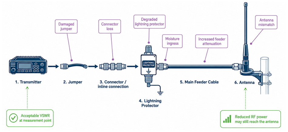
The exact operational effect will depend on the original link margin, site configuration, terrain and building environment. However, any additional feeder loss can consume valuable coverage margin, particularly in locations that were already close to the limits of reliable service.
Key Engineering Insight
VSWR can remain stable while the usable performance of the RF system declines.
Common Causes Of Feedline Degradation And The Hidden Costs
Feedline loss is one of the most underestimated failure modes in LMR systems. Feedline problems do not always appear as sudden or complete failures, but can develop gradually and remain undetected during basic transmitter checks. Potential causes include:
- Water ingress at connectors, joints or weather seals
- Corrosion at exposed terminations
- Ultraviolet degradation of cable jackets
- Mechanical stress caused by wind or mast movement
- Poor connector installation or insufficient torque
- Damage caused during maintenance work
- Ageing dielectric materials
- Deterioration of lightning protection devices
- Faults within jumpers or flexible cable sections
These issues may increase insertion loss while leaving the impedance match broadly acceptable. As a result, transmitter diagnostics may continue to show the expected forward power and an acceptable VSWR, even though the effective RF power available at the antenna has decreased. This disconnect between transmitter status and antenna-system performance is one reason that intermittent coverage problems can be difficult and time-consuming to diagnose.
Why Digital LMR Systems Can Make RF Degradation More Noticeable
Digital LMR technologies such as DMR, P25 and TETRA do not always exhibit the same gradual change in perceived audio quality associated with analogue FM systems.
When a digital signal is comfortably within the available link margin, communications may remain clear and consistent. As the signal approaches the usable operating threshold, errors and intermittent dropouts may become more frequent. Once the signal falls below that threshold, intelligibility or service may be lost rapidly.
Depending on the network architecture and overall system design, declining RF performance may appear as intermittent audio or data dropouts, reduced coverage in previously reliable service areas, or inconsistent portable-radio performance inside buildings. Users may also experience unreliable communications at the edge of the coverage area, poor service despite apparently adequate signal levels, or changes in network behaviour such as increased retry activity.
Measurements That Provide A More Complete Picture
A modern LMR maintenance strategy should treat VSWR as just one element of a broader RF diagnostic framework.
Forward and
Reflected Power
Confirms transmitter performance under real load conditions and identifies unexpected power loss early.
Return Loss / VSWR
Still essential for identifying gross mismatches, antenna faults, and installation issues.
Insertion Loss Measurement
Critical for quantifying real RF delivery to the antenna - often the missing link in field diagnostics.
Distance-to-Fault (DTF)
Allows engineers to pinpoint faults along the transmission path, reducing troubleshooting time from hours to minutes.
Baseline
Trending
Comparing current measurements against installation baselines to detect slow degradation before it becomes service-impacting.
Building Measurement Confidence With Bird RF Test Solutions
Effective LMR maintenance depends not only on the range of measurements available, but also on confidence in the measurement process. Field engineers require equipment that supports repeatable measurements, is practical to use at radio sites, and enables abnormal conditions to be identified clearly. It should also help isolate faults quickly, allow consistent comparison with baseline results, and provide a reliable assessment of both transmitter and antenna-system performance.
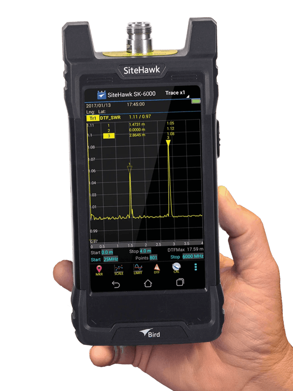
Bird provides RF test and measurement solutions designed to support transmitter verification, power measurement and antenna-system analysis.
When RF power measurement is combined with cable and antenna analysis, engineers can develop a broader view of both transmitter operation and RF delivery through the antenna system.
Bird SiteHawk cable and antenna analysers can support measurements including return loss, VSWR and Distance-to-Fault analysis. Appropriate Bird power-measurement equipment can be used to assess forward and reflected RF power.
The exact instrument and measurement configuration will depend on factors including:
- Operating frequency
- Transmitter power
- Connector type
- Required measurement accuracy
- Site access
- Whether testing is performed online or offline
- The complexity of the installed antenna system
VSWR Is Essential, But It Is Not The Whole Story
VSWR remains a valuable measurement for LMR installation, commissioning and maintenance.
It can identify impedance mismatch and provide an important indication of antenna-system condition. However, it does not independently confirm feeder loss, power delivered to the antenna or overall RF performance. By examining the complete RF transmission path, maintenance teams can detect developing faults earlier, reduce troubleshooting time and protect the coverage margin on which reliable communications depend.
Speak to an LMR Measurement Specialist
APC provides access to Bird RF test and measurement solutions for the installation, maintenance and fault-finding of Land Mobile Radio systems. Our team can help you identify suitable equipment for measuring RF power, evaluating cable and antenna systems, locating faults and establishing repeatable site-maintenance procedures.
Discuss your LMR measurement requirements with one of our expert team:
0330 313 3220 | [email protected]
David West | Head of Test & Measurement Solutions

David leads the delivery of advanced test, measurement and engineering solutions to customers operating at the forefront of technology. With extensive experience spanning EMC, RF and electronic test, David has spent his career helping organisations overcome complex measurement challenges across defence, aerospace, automotive, telecommunications, industrial and research sectors.
Combining a strong technical background in electromagnetic compatibility (EMC) testing with commercial leadership, David works closely with manufacturers, systems integrators and test laboratories to develop practical solutions that improve product performance, accelerate compliance and reduce development risk. His expertise extends across the broader test and measurement landscape, including RF and microwave measurement, power electronics, automated test systems and emerging technologies.
A recognised industry voice, David regularly writes on the latest trends and challenges in test and measurement, translating complex engineering topics into practical insights that help organisations make informed technical decisions and maximise the value of their investment in measurement technology.