Anechoic Chambers
Custom EMC Anechoic Chambers designed, built and tested to your requirements.
APC’s specialist team is here to support product designers and engineers in overcoming unintentional EMC issues, resulting in unwanted effects such as electromagnetic interference (EMI) or even physical damage in operational equipment, our team offer a range of EMC testing solutions from some of the world’s leading manufacturers.
What is an Anechoic Chamber?
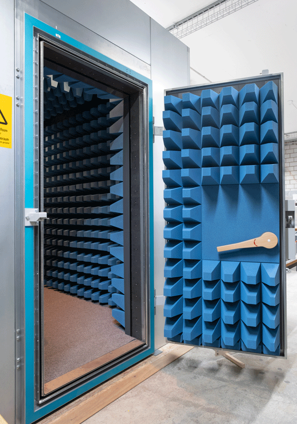
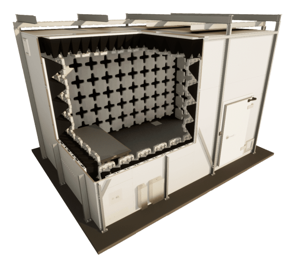
Anechoic Chambers are the ultimate testing ground for engineers and scientists looking for precise Radio Frequency (RF) and Electromagnetic interference (EMI) measurements. These specialised enclosures contrast two elements designed to minimise RF noise from the external environment and minimise reflections from within the chamber.
This particular construction features walls, ceilings and floors lined with highly effective anechoic materials, which essentially "absorb" Radio Frequency waves, preventing RF from the test device from being reflected from the walls to RF measurement equipment.
The resulting environment approximates a free-field condition, allowing RF waves to propagate outward from the source object with minimal distortion. By eliminating reflections, anechoic chambers empower researchers to better understand a product's RF performance, leading to improved design and RF noise reduction strategies.
Anechoic Chamber UK Suppliers
APC, in partnership with ETS-Lindgren, provide a wide range of Anechoic Chambers for the UK market.
Anechoic Chambers are used by a wide range of industries for testing and measuring electromagnetic compatibility, antenna testing, wireless device testing and other related applications.
At APC we see projects through from specification through to sign-off and handover.
How big does an Anechoic Chamber need to be?
For RF and microwave testing, an anechoic chamber typically needs to be large enough to accommodate the device under test and the measurement equipment, as well as allow for sufficient space between the device and the chamber walls. The size of the chamber will also depend on the frequency range being tested, as higher frequencies require shorter wavelengths and therefore smaller test distances.
For example, an anechoic chamber used for testing cellular phone antennas at 900 MHz may be smaller than one used for testing radar antennas at 10 GHz. In general, anechoic chambers for RF and microwave testing can range in size from small, portable units to large, custom-built chambers.
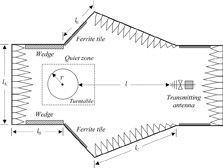
What is a Quiet Zone in an Anechoic Chamber?
The quiet zone in an RF microwave anechoic chamber is the area within the chamber where the EMF level is minimised. This area is typically located in the centre of the chamber and is where measurements of RF and microwave devices are taken. The size of the quiet zone depends on the size and shape of the chamber, as well as the frequency range of the electromagnetic waves being absorbed.
How are Anechoic Chambers tested?
There are several methods used to test RF anechoic chambers, including:
- Frequency response measurement
The frequency response of an RF anechoic chamber can be measured using a signal generator and a spectrum analyzer. The signal generator is used to transmit a test signal at different frequencies, and the spectrum analyzer is used to measure the strength of the signal as it is received at different locations within the chamber. - Antenna pattern measurement
The antenna pattern of an RF device can be measured using an RF anechoic chamber. This is typically done using a network analyzer and an antenna positioner, which allows the antenna to be moved to different positions within the chamber. - Isolation measurement
The isolation between two antennas within an RF anechoic chamber can be measured using a network analyzer. This allows for the determination of the amount of interference that may be present between the two antennas. - Absorption coefficient measurement
The absorption coefficient of an RF anechoic chamber can be measured using a network analyzer and a test signal at different frequencies. The absorption coefficient is calculated based on the intensity of the signal at each location within the chamber. - Modal analysis
Modal analysis can also be used to test RF anechoic chambers. This is typically done using a network analyzer and specialised software that analyzes the resulting RF data. - Visual inspection
A visual inspection of the chamber can also be useful in identifying any potential problems or areas that may need attention. This might include checking for any damage to the chamber walls or floor, as well as inspecting the chamber’s absorber panels for any signs of wear or damage.
Design, materials and specifications

What is Absorber Material used inside EMC Chambers?
RF pyramidal absorber is a low-density polyurethane foam specifically designed to reduce radio frequency reflections by transferring electromagnetic waves into heat energy. Depending on the frequency range they vary in size from 60mm to 1520mm in height, MDL offers an ETS-Lingren absorber series that can cover 80Mhz – 40GHz with minimal guaranteed reflectivity.
What are Ferrite Tiles used for?
Anechoic chambers can also be lined with ferrite tiles, these tiles are typically made from sintered ferrite and include a dielectric backing layer. This creates a optimum low and high-frequency return loss performance. They typically cover between the ranges of 30 MHz to 1 GHz and may be accompanied by the pyramidal absorber if the required frequency is above 1GHz.


Wave Pipe Penetrations
A waveguide feed-through, also known as a pipe penetration, is a device used to allow a waveguide to pass through a shielded wall or barrier while maintaining a high level of electromagnetic interference (EMI) and radio frequency interference (RFI) shielding. Waveguides are used to transmit electromagnetic signals at high frequencies and are commonly used in microwave and radar systems.
- Accommodate requirements such as fire suppression systems, hydraulics and other utilities
- Honeycomb waveguide insert option available for high frequency or gaseous applications
- Dielectric unions are available to maintain isolation to the ground
Wave Guide Feed-through
A waveguide feed-through consists of a metallic pipe that passes through a hole in a shielded wall or barrier, with the waveguide inserted into the pipe. The feed-through has a removable centre plug allowing fibre optic cables with connectors to be brought into a shielded enclosure.
- The central plug bore accommodates ST and SMA connectors
- All connectors can be installed into a shielded enclosure while maintaining 100 dB attenuation at 18 GHz
Wave Guide Air Vents
EMI/RFI shielded waveguide air vents are used to provide ventilation to shielded enclosures or and rooms, while at the same time preventing electromagnetic interference (EMI) and radio frequency interference (RFI) from entering or leaving the enclosure. These air vents are typically used in electronic equipment and facilities, where EMI/RFI can cause incorrect readings or malfunctions.
The waveguide structure of the air vent is carefully designed to attenuate electromagnetic waves over a wide range of frequencies. This means that EMI/RFI signals in the environment pass through the air vent are significantly reduced.

- Available in 3.175 mm (1/8 in) and 4.76 mm (3/16 in) Honeycomb Cell Geometry
- Adaptable to a variety of mounting flanges and gasket techniques
- Brass or steel core material with tin coating for superior RF performance and corrosion resistance
- Minimal air flow resistance and pressure drop
- Continuous solder-fused for superior strength and RF performance

RF Doors
APC provide ETS-Lindgren RF Shielded doors for a wide range of applications with attenuation of up to 100dB at 40GHz. ETS offer a range of doors from manual or pneumatic swing doors which can be single and double and available in standard or custom sizes to sliding doors and all-weather doors where an exterior RF-shielded door is required.
Overall, radio frequency shielded doors are an important component of many modern facilities that rely on sensitive electronic equipment or need to protect against external RF interference.
- Easy to operate
- Patented hinges allow final closing movement to be parallel to door frame
- Permit normal swing when fully opening door
- Final RF seal obtained by cam followers
- Optional pneumatic operation
EMC Chambers, SCIFs and Shielded Enclosures by APC
APC also provide bespoke deployable SCIFs and RF Shielded Containers to meet the demanding requirements imposed on critical systems and infrastructure.

,-Semi-Anechoic-(SAC)-AND-Open-Area-test-Site-(OATS)")


Start a technical conversation with our team to discuss your EMC projects
APC Technology Group prioritises understanding and exceeding our customers' specific EMC testing requirements. We achieve this through a collaborative approach, tailoring solutions to meet each client's unique specifications, ensuring timely delivery and adhering to established budgets.
Request a callback from a member of our team to get dedicated one-to-one consultancy with your latest projects and applications.